[CAN 04] - Gripper Motor Control with CAN Bus
Single-motor gripper control with ESP32, SimpleFOC, and SocketCAN
Code: [GitHub]
Previous Posts:

The previous posts configured SocketCAN on Ubuntu and established communication with an ESP32. This post extends that setup to control a one-DOF robotic gripper using the SimpleFOC Arduino library.
This work was completed in collaboration with Roboligent using its Optimo robot manipulator.
Hardware


- SimpleFOC Mini
- HT2205 with AS5048A Encoder — used for bench testing, not in the final gripper
- TJA1050 CAN Transceiver
- ESP32 Dev Board
- Makerbase CANable 2.0 USB to CAN adapter
Wiring

-
The ESP32 and CAN-transceiver wiring follows the previous post. Some TJA1050 modules and USB-to-CAN adapters include a switchable 120 Ω termination resistor. With the system powered off and two correct 120 Ω terminators installed—one at each physical end of the bus—the resistance measured between CAN-H and CAN-L should be approximately 60 Ω.
-
Connect the motor phases to the SimpleFOC Mini’s M1, M2, and M3 outputs. Phase order and sensor direction must be consistent with the FOC configuration; an incorrect combination can reverse the direction or prevent reliable commutation. Rerun the library’s motor/sensor alignment procedure after changing the phase wiring. The driver also requires a separate motor supply; this test used 12 V for the HT2205.
-
Connect
IN1,IN2,IN3, andENto the configured ESP32 GPIO pins, and connect the logic grounds. -
Power the SPI encoder at a voltage supported by both the sensor and the ESP32 logic interface. Connect
MOSI,MISO,SCLK, and chip select to the configured SPI pins. Default pin assignments vary by ESP32 board; the following sketch prints the Arduino core’s defaults:
void setup() {

  Serial.begin(115200);
  Serial.print("MOSI: ");
  Serial.println(MOSI);
  Serial.print("MISO: ");
  Serial.println(MISO);
  Serial.print("SCK: ");
  Serial.println(SCK);
  Serial.print("SS: ");
  Serial.println(SS);
}

void loop() {
}
-
For a magnetic encoder, follow the sensor datasheet’s magnet geometry, alignment, field-strength, and air-gap requirements. Excessive axial or radial misalignment can reduce accuracy or produce invalid readings; a single nominal gap is not sufficient without considering the selected magnet.
-
Multiple SPI encoders may share
MOSI,MISO, andSCLKwhile using separate chip-select lines. Keep the wiring short, provide a solid return path, and reduce the clock if ringing or read errors appear. The AS5048A specifies a minimum serial-clock period of 100 ns, corresponding to a 10 MHz maximum clock; 80 MHz is outside its specification. SimpleFOC defaults to 1 MHz, which is a sensible starting point. Splitting devices across the ESP32’s SPI peripherals can also simplify timing and chip-select management.
Flashing the Arduino Code
Install the SimpleFOC and Arduino-CAN libraries in the Arduino IDE.

The prototype sends a desired torque command from the host to the ESP32 and returns the measured motor position. Classic CAN provides at most 8 payload bytes per frame, so one 64-bit value fills the entire payload.
For a homogeneous prototype in which both endpoints use the same 64-bit IEEE-754 representation and byte order, memcpy can copy a double into an 8-byte buffer without violating C++ aliasing rules:
void packDouble(double value, uint8_t dataBuffer[8]) {
    static_assert(sizeof(double) == 8, "Protocol requires a 64-bit double");
    memcpy(dataBuffer, &value, 8);
}
Raw memory layout is not a portable wire protocol: it leaves endianness and floating-point representation implicit. A production protocol should define the byte order and scaling explicitly. For example, torque and position can be converted to fixed-width integers with documented units before serialization. This also leaves room for status flags, sequence numbers, or multiple signals in one frame.
When a command arrives, the ESP32 maps desired torque to the target supported by the configured torque controller. With closed-loop current control and an identified torque constant, this can be a q-axis current target; a voltage-mode setup should not be presented as calibrated torque control. In either case, the sign convention, units, limits, and command-timeout behavior should be part of the protocol definition.
The host can use a small C++ SocketCAN interface to encode commands and decode feedback. The Linux SocketCAN documentation is the authoritative reference for the socket API.
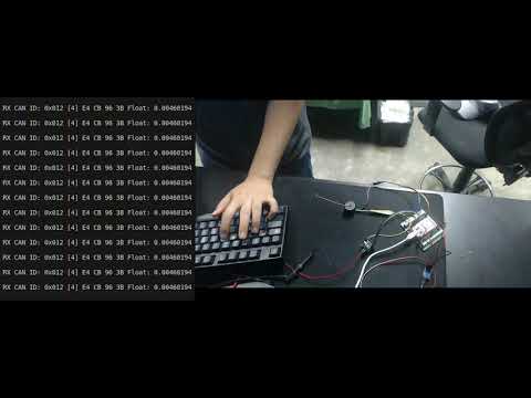
Now we can control the gripper motor using the same setup.
The belt transmission converts motor rotation into symmetric linear motion of the two gripper jaws.

The arm and gripper trajectories were recorded through kinesthetic teaching—manually guiding the robot—and then replayed to push and grasp the Jenga block.