1. A transmission element that bends
In a transmission made of gears, shafts and links, the path of the force is fixed by the shape of the parts. To bring the motor’s rotation to a joint, the gap must be bridged with rigid parts, so the motor and gearbox usually sit close to the joint. This layout is easy to modularize and keeps the load path short, but the mass of the motor and gearbox rides on the link.
A cable bends. Because it can turn corners over pulleys and guides, the motor can sit in the torso or a proximal link and only a light cable runs to the joint. This is called remote actuation (or proximal actuation). The further the motor is from the joint, the less mass and inertia the moving link carries.
In robotics, actuation with cables is called cable-driven or tendon-driven. “Cable” usually refers to the flexible part that carries the force, and “tendon” emphasizes its role of pulling a joint, but the two terms are used interchangeably in the literature. This series uses them with the same meaning.
A cable can also act as a reducer. If two drums of different radii are connected by a cable, the length wound on one drum must equal the length paid out from the other, so when the small drum turns several times the large drum turns only a little. The speed drops and the torque rises by the same ratio. With no gear teeth, there is no gear backlash either.
So choosing cables also decides where the motors go and how the joints are driven: the actuation architecture of the robot.
The basic ways to drive a joint with cables come down to three choices.
- Drive. A cable can only pull. To move a joint in both directions, either two cables pull in opposite directions (antagonistic tendons), or one cable pulls and a spring returns the joint (tendon + return spring). In the antagonistic layout both cables must stay taut for the output to follow immediately when the direction reverses. The return-spring layout saves one cable and one motor, and leaves the return motion to the spring.
- Output. With a pulley on the joint and the cable wound on it, the moment arm is the pulley radius and stays constant. Fixing the cable end directly to the link removes the pulley, but the distance between the cable and the joint, i.e. the moment arm, changes with the joint angle.
- Layout. Running the two strands parallel turns the input and output in the same direction; crossing them turns them in opposite directions.
The example below combines the three choices so you can compare how the input reaches the output.
Combine layout, drive and output
Implementation details
Teaching kinematics model: inextensible cables, no slip on the pulleys, cable ends fixed to the pulleys (dots). With equal radii the change in wrap angle becomes the output rotation one to one. Tension, friction and cable stiffness are not modeled. In return-spring mode θ_out = 0 is where the spring rests against a stop, and the return after release is drawn as a first-order response with a 0.9 s time constant (not computed from a spring stiffness and inertia). The sag of a slack tendon only illustrates the excess length. The input range is ±175°.
2. Case study: LIMS and LIMS2-AMBIDEX
An example that uses both remote actuation and cable reduction is LIMS (Low-Inertia high-stiffness Manipulator), a robot arm from Prof. Yong-Jae Kim’s lab at KOREATECH 1. This work continued, through joint research with NAVER LABS, into the dual-arm robot LIMS2-AMBIDEX 2, 3.
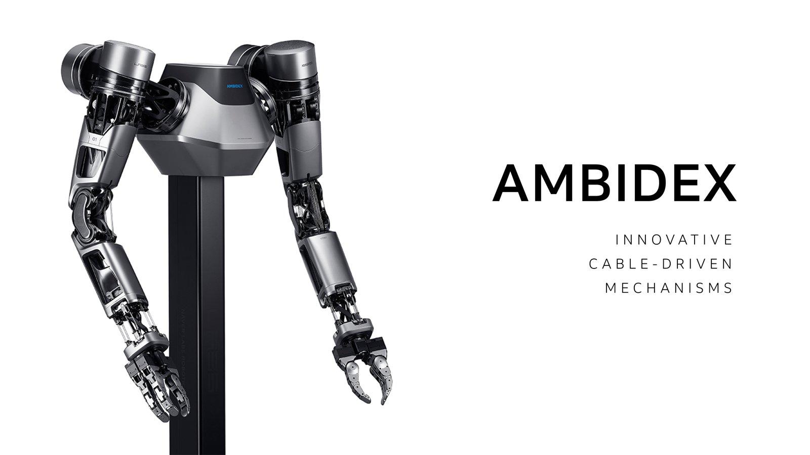
The LIMS robots place the heavy actuators in the shoulders and torso and drive light arms with cables 2, 3. As a result, the mass and inertia beyond the shoulder are lower than those of a human arm 1. Lower moving mass and inertia mean less kinetic energy stored at the same speed, which makes a collision with a person safer 4.
Driving a light arm with cables raises a stiffness problem. Cables stretch, so the joints tend to become compliant, and joint stiffness is closely tied to position-control performance. LIMS addresses this with a lightweight tension-amplification mechanism, raising the joint stiffness while keeping the arm light 1.
The LIMS robots make the arm light through remote actuation and give stiffness back to that arm through cable-based tension amplification. This combination suits a robot that has to move fast in an environment where it may collide with people.
Then why don’t all robots use cables?
3. Moving versus moving well for a long time
The principle of pulling a joint with a cable is simple. As in the example above, turning a drum winds the cable, and the cable pulls the joint. The hard part is meeting the desired reduction ratio, stiffness, transparency and size at the same time. The more the cable is asked to do both reduction and remote transmission, the more often changing one condition moves another.
ETH Zurich’s Capler-Leg drives a leg joint with a single-stage cable–pulley transmission. It transmits torque transparently and without backlash, but at high torque the cable stretched and the output angle changed 6.
A cable transmission can be transparent, but it is not a rigid, inextensible transmission. And there is a gap between a prototype that runs well a few times on the test bench and a transmission that keeps the same tension and the same transmission characteristics after many cycles.
4. Design conditions of a capstan drive
4.1 Principle
The capstan drive is a typical cable reducer. A small input drum of radius and a large output drum of radius are connected by a cable. If the cable does not stretch or slip, the length wound on one side must equal the length paid out on the other.
The reduction ratio and the torque ratio are therefore set by the ratio of the drum radii.
With no meshing teeth there is almost no backlash, and the low friction makes it easy to get backdrivability, where pushing on the output turns the motor. The name comes from devices that hold a large rope tension through friction on a drum, but robot capstan drives may wind the cable several times and fix both ends to the drums to constrain the length relation 6.
4.2 Beyond the reduction ratio
The equation is one line, but an actual design has to settle more than the reduction ratio. Here we look at four conditions.
- Tension vector: what load does the pretension put on the shaft and bearings?
- Lead angle and fleet angle: does the cable follow the path it was designed for?
- Cable walk and drum geometry: is there enough room for the cable to wind and move?
- Pretension and termination: how are the tension and the cable ends held stable?
4.3 Tension vector
The first is the direction of the tension (tension vector).
Cables are installed with an initial tension (pretension) so that they do not go slack during operation. This tension does more than produce torque on the drum: it also pulls the shaft and bearings in the direction the cable leaves. So with the same pretension, the force on the shaft depends on which side of the drum the cable is wound on and how the two drums are arranged.
If the two tensions act in nearly opposite directions, the pretension resultant cancels when the drive is idle, which reduces unnecessary load on the shaft and bearings. If the two tensions have components in the same direction, those components add instead of cancelling, and the shaft and bearings are loaded even when the motor transmits no torque.
Equations: resultant of the two tension vectors
For a simple layout in which the resultant can be written from the tensions of the two free spans, the force on the shaft is the sum of the two tension vectors.
Here are the unit vectors along which the two cables pull the shaft. If both cables carry the same pretension and the angle between the two tension vectors is , the magnitude of the resultant is
It cancels for , when the two tensions are opposite, and grows as the two vectors point to the same side. When each strand makes the angle with the centre line, as in the example below, and the resultant is . The actual shaft reaction also depends on the full path of the cable around the drum, the terminations and other external forces.
Note that the reduction ratio is not what sets this resultant. Even at 1:1, a resultant appears if the two tension vectors point to the same side. Whether the strands are crossed does not decide it by itself either. Neither open nor crossed is good or bad in itself. What sets the resultant is the cable path and the direction of the tangents where the cable enters and leaves the drum.
In some layouts, a larger distance between the drums turns the entry and exit directions unfavourably and the resultant grows. The example below marks, at the drum centre, the directions in which the two strands pull the shaft and the resultant ΣF for equal pretension in both strands. In the crossed layout, increasing the centre distance turns the two strands toward the same side and the resultant grows. In the open layout the two strands leave the same side of the drum and run side by side to the pulley, so the resultant stays large even at the minimum centre distance. These results come from the path geometry chosen in the example; with the same open or crossed layout, the resultant changes with which side of the drum the cable is wound on and where it is sent.
Tension direction and cable walk
Implementation details
Teaching kinematics model. Drum radius r = 10 mm. Red and blue are separate cables, each terminated on the drum at one end and on the output pulley at the other (dots; hollow in the top view when on the underside). The two cables share one helical groove on the drum, with a 180° gap between their drum terminations. Turning the drum winds one cable on and pays the other out by the same length. The number of turns is chosen so that the paying-out strand keeps 30° on the drum at the end of the input range, or more when needed to keep the red and blue groove regions on the output pulley at least one cable diameter + 0.5 mm apart over the whole stroke. The cable is inextensible and does not slip on the drum or the pulley. In the crossed layout both strands follow the internal tangents, so sin β = (r + R) / d and θ_out = −θ_in / N; in the open layout they follow the external tangents, so sin β = (R − r) / d and θ_out = θ_in / N. The pitch p is the axial advance per drum turn and the lead angle is tan λ = p / 2π(r + d_c/2) (cable diameter d_c = 1 mm, p ≥ d_c). The output pulley has a helical groove of matched lead (pitch N·p), placed so that each free span leans by λ (α_f = λ). The pulley side moves by the same distance as the drum side, so the free span translates parallel and α_f = λ is kept. Both angles are measured from the plane normal to the axis, positive in the direction the helix carries each strand off the drum. The groove spacing on the pulley follows the pitch and β, so moving those sliders amounts to redesigning the pulley. The top view is stretched 3× along the drum axis, so the lean in the drawing looks larger than the true fleet angle; the value α_f uses the true free span length L. The only force computed is the resultant for equal pretension in both strands; the tension difference from torque, friction and the capstan effect are not modeled. The cable diameter is fixed at 1 mm and used only for the pitch angle and the minimum pitch, not in the drawing. The output range is ±120°.
During operation the two tensions differ, so perfect cancellation does not hold. What matters is arranging the cables so that pretension not needed for torque transmission does not create unnecessary structural load 7.
The distance between the drums also affects stiffness. The longer the same cable, the more it stretches under the same tension, so moving the drums apart makes the transmission softer (the axial stiffness of a linear elastic cable is ). In short, the cable length sets the compliance of the transmission, and the cable path sets how the pretension loads the structure.
Being able to drive a distant joint with cables does not mean the two reduction drums must also be far apart 7. Doing both on one cable path means meeting these geometric constraints as well, so it is sometimes more reasonable to separate reduction and remote transmission into different stages. Designing a capstan drive means deciding not only the two drum radii but also where the cable goes, in which direction it pulls, and which structure takes that force.
4.4 Lead angle and fleet angle
How the cable winds on the drum also matters. Winding the cable several times on the small input drum provides contact length and reduces the load concentrated at the end. To wind several turns without overlap, the cable has to follow a helix that advances by a fixed pitch along the axis per turn (the next section explains why). The slope of this helix is the lead angle. On a drum with a machined helical groove, the lead angle is constant.
The fleet angle, on the other hand, measures how far the actual direction in which the cable enters or leaves the drum deviates from the reference plane normal to the drum axis. The lead angle is the winding geometry designed into the drum; the fleet angle is the actual direction set by the layout of the drum and the surrounding mechanism.
On a grooved drum the two directions have to match. A large difference makes the cable press against the groove wall, increasing friction and wear, and in the worst case the cable jumps out of the groove 7. Strictly, one should not compare two angles measured in the plane normal to the axis but look at the three-dimensional angle between the actual cable direction and the groove tangent; is a simplification of that condition in one reference plane. Besides making room to wind the cable, check that the direction the cable is designed to wind in matches the direction it is actually pulled.
Equations: lead angle and fleet angle
Winding on a drum of radius while advancing along the axis per turn gives the lead angle
With an axial offset of the cable and a free span length , the fleet angle is approximately
With the same reference plane and sign convention, the ideal alignment for a grooved drum is .
There is a trade-off here as well. Moving the drums apart reduces the fleet angle for the same axial offset. But as seen above, a longer free span lowers the stiffness of the transmission. Neither short nor long is always the answer. Lead and fleet angle are also a different problem from the tension vector. Both concern the cable path, but the tension vector deals with the resultant in the plane normal to the drum axis, while the lead and fleet angles deal with the inclination along the axis.
4.5 Cable walk and drum geometry
When the cable is wound several times, winding it over itself makes the turns press and rub against each other. Cable sliding on cable causes abrasion, and a section riding on another turn has a different winding radius, which disturbs the reduction ratio.
So the cable is wound at an angle along a helix so that the turns do not overlap. It advances by one pitch along the axis per turn, and the pitch is made larger than the cable diameter so that neighbouring turns do not touch. Usually a helical groove machined into the drum sets this path. The slope of this helix is the lead angle from the previous section.
The groove is fixed on the drum, but as the drum turns one cable winds onto the groove and the other pays out by the same amount. The point where the cable winds onto and leaves the drum (the take-up point) therefore moves along the axis by one pitch per input turn. This is cable walk. Turning the input angle to its limit in the example above shows, in the top view, the points where the two cables leave the drum moving sideways.
The input drum must therefore be long enough along the axis to hold the length of the wound helix plus the distance the helix walks over the input range. The more turns, and the more the input drum turns because of a large reduction ratio, the longer the drum.
Equations: required drum length
With pitch , number of wound turns and total input rotation range (rad), the drum needs roughly
not counting the margin for the terminations. The first term is the length taken by the wound helix, the second the range of cable walk. For neighbouring turns not to touch, must exceed the cable diameter .
Walk also changes the fleet angle. If the output pulley has plain circumferential grooves, the grooves stay in place, so the free span tilts as the input-side helix moves sideways and drifts away from the lead angle toward the ends of the stroke. If the output pulley also has a helical groove with the same lead angle, and the handedness and axial travel of the two grooves, the direction in which the cable enters and the initial axial positions all match, the pulley-side entry point moves by the same distance. The free span then translates parallel while keeping its inclination. The output pulley in the example above is this case, and the fleet angle stays equal to the lead angle even at the ends of the input range.
The wrap on the output pulley also changes over the stroke. As the output pulley turns, one strand winds further on and the other unwinds. The point where the unwinding strand comes close to its termination sets the range of motion of the joint. In the example above, too, one strand is nearly gone from the pulley when the output angle reaches its limit.
The drum diameter also has to be chosen. A larger reduction ratio needs a smaller input drum, and the smaller the drum, the smaller the radius the cable bends around. The desired reduction ratio and the bend radius the cable can tolerate have to be matched together.
4.6 Pretension and termination
The last question is how to hold the tension and the cable ends. How much pretension is needed? And do the tension and transmission characteristics set at assembly still hold after repeated motion?
The cable ends have to be fixed to the drums. Ordinary knots may not be robust enough under long-term cyclic loading, and a single eye splice may not withstand creep, so multiple splices are sometimes used 6.
All of this, just to get one reduction ratio.
4.7 Planar mechanisms
Not every cable mechanism is this complicated. If, as in the example in Section 1, the cable wraps less than one turn on each pulley and both ends are fixed, the cable path can stay in one plane from end to end. With no wound cable moving sideways, there is no need for a helical groove, a lead angle or cable walk. This follows from choosing a structure in which the cable path stays in one plane, not from the name “planar mechanism” itself. If the grooves of the two pulleys lie in the same plane, the fleet angle also stays at zero.
There is a cost. Because the input rotation is limited to less than one turn, a larger reduction ratio leaves a smaller output range of motion. The contact length available for wrap friction is also shorter, so the terminations take the load more directly.
4.8 The remaining problem: the cable itself
Simplifying to a planar mechanism avoids many design constraints. But it does not solve every problem.
What we have looked at so far is where to place the cable, how to wind it and in which direction to pull it. We have not yet said anything about the cable itself.
We have been assuming that the cable is an ideal transmission element that does not stretch and whose properties do not change under repeated bending. In practice, the choice of cable can change the performance and service life of every design above.
5. Cable specification
The tighter the constraints of the mechanism, the less freedom there is in choosing the cable. In a tight space, the cable diameter and bend radius are the first limits. To transmit a large load, strength and safety margin matter. If the output position has to be transmitted precisely, how much the cable stretches under load becomes a condition. For a robot that runs repeatedly, the behaviour after long use matters as well. With the same drive architecture, the choice of cable changes what can be designed and how well it performs.
So one turns to the manufacturer’s datasheet. Typical items are:
- Minimum breaking strength
- Nominal diameter
- Elongation or effective stiffness
- Bending conditions such as a recommended minimum bend diameter
- Durability information for given operating conditions (when provided)
Not every datasheet lists the same items. Samson’s product page for the HMPE rope AmSteel-Blue lists the weight per diameter, average and minimum breaking strength and ISO 2307 strength, and gives the elastic elongation at several load levels 8. Guidance on bending is not on the product page but in a separate document, as a general warning that static strength and service life decrease as decreases 9. The product page for LIROS’s Dyneema cord D-Pro, available from 1 mm diameter, gives the diameter, breaking strength and “working stretch < 1%”, with no test standard or bending conditions 10.
6. Limits of a datasheet
Datasheet values assume specific test conditions and measurement methods. They usually come from pulling a straight specimen fixed in a defined way. This is why the Samson page states separately that the ISO 2307 strength is for unspliced rope and the other strengths are for spliced rope 8. Changing only how the ends are fixed changes the strength value of the same rope.
A cable in a robot is not only pulled straight. It wraps around pulleys, bends, moves over the same section repeatedly and touches other parts. Properties from a standard test do not by themselves determine the properties of the installed transmission. This does not mean the datasheet is wrong. A datasheet answers a defined test, and it may not carry enough information to describe the actual operating conditions.
We use cables because they bend. And that very bending makes the behaviour of the cable complicated.
What changes when a cable bends?
Next post: Cable 02 — What Changes When a Cable Bends
References
[1] Y.-J. Kim, “Anthropomorphic Low-Inertia High-Stiffness Manipulator for High-Speed Safe Interaction,” IEEE Transactions on Robotics, 33(6), 1358–1374, 2017. DOI: 10.1109/TRO.2017.2732354.
[2] H. Song, Y.-S. Kim, J. Yoon, S.-H. Yun, J. Seo, and Y.-J. Kim, “Development of Low-Inertia High-Stiffness Manipulator LIMS2 for High-Speed Manipulation of Foldable Objects,” 2018 IEEE/RSJ International Conference on Intelligent Robots and Systems (IROS), 4145–4151, 2018. DOI: 10.1109/IROS.2018.8594005.
[3] NAVER LABS, “AMBIDEX, robot arm with innovative cable-driven mechanisms,” blog post, 2017-10-16. Link. Source of the dual-arm photo (no license stated).
[4] Y.-J. Kim, “Design of low inertia manipulator with high stiffness and strength using tension amplifying mechanisms,” 2015 IEEE/RSJ International Conference on Intelligent Robots and Systems (IROS), 5850–5856, 2015. DOI: 10.1109/IROS.2015.7354208.
[5] IRIM LAB KOREATECH, “LIMS2-AMBIDEX mechanical design,” YouTube video. Link.
[6] J. Hwangbo, V. Tsounis, H. Kolvenbach, and M. Hutter, “Cable-Driven Actuation for Highly Dynamic Robotic Systems,” arXiv:1806.10632, 2018. Paper.
[7] Stanford CS235, “CS235: Applied Robot Design, Lecture 7-Introduction to Cable Transmissions,” YouTube video, 2012-04-24. Link. 21:08–25:39 pretension resultant versus cable path and drum spacing; 26:01–29:16 separating reduction and remote transmission; 33:14 lead angle; 49:14 fleet angle.
[8] Samson Rope Technologies, “AmSteel-Blue,” product page. Link. Accessed 2026-11-16.
[9] Samson Rope Technologies, “Warning statement” (rope use and bending guidance). Link. Accessed 2026-11-16.
[10] LIROS GmbH, “D-Pro 1 mm,” product page. Link. Accessed 2026-11-16.