[Robot Hardware 01] - What Is Robot Hardware?
Robot hardware from a Physical AI perspective - Introduction
What Do We Mean by Robot Hardware?
When people hear “robot hardware,” they usually think first of visible components such as motors and frames. In the dictionary sense, hardware simply means the physical components of a system.
In a multi-jointed robot, however, hardware includes much more than the drive mechanisms, sensors, and control PC. It also includes the microcontrollers and embedded systems that control motors at high frequency, the network architecture used to communicate with the control PC, physics-model-based control such as gravity compensation, and even floating-base CoM (Center of Mass) control or optimal-control-based controllers that provide basic stability for legged robots. In robotics, these elements are often discussed together as the “hardware level.”
Strictly speaking, many of these elements are software. But without them, the robot cannot even reach a state in which experiments or data collection are possible.
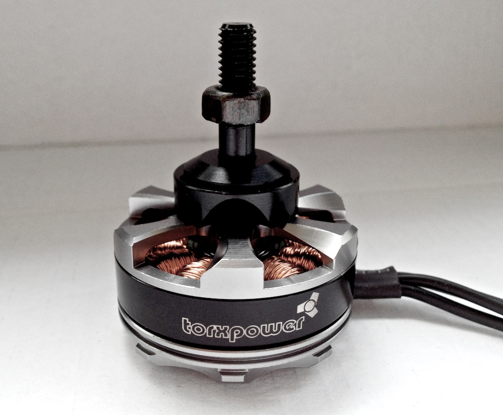 BLDC motor that converts electrical energy into rotational joint torque [1]
 If we think of robot hardware as simply “a machine with many motors,” we miss an important part of the picture. From the perspective of Physical AI, a robot is closer to an intelligent system that interacts directly with the physical world than to a machine that merely executes commands. The robot applies force, the environment changes in response, and the robot senses that change again. Hardware is always at the center of this interaction.
Even when multi-jointed robots look similar, the way they interact with the environment can differ substantially from one hardware platform to another. With the same apparent joint structure, the reducer type, material, and reduction ratio change backdrivability—the ability to yield to external force—and mechanical impedance. These properties determine whether the robot reacts rigidly or softly at the moment of contact.
Once the mass distribution and inertia of the entire robot are added, the actual forces and accelerations produced by the same control input can be completely different. In tasks with repeated contact, especially manipulation and locomotion, these differences directly affect system stability and task success rate.
The same is true of sensing and control. Control period, communication delay and noise, sensor sensitivity and linearity, and hysteresis all have a major effect on control performance. Add structural stiffness, joint stiffness, and friction, and the robot’s interaction with the world becomes the precise result of many coupled classical-mechanical and electromagnetic properties.
AI and Robot Hardware
The complexity of robot hardware is not merely a mechanical inconvenience. It is a fundamental barrier to applying modern AI algorithms. This barrier appears most clearly in two forms: the Sim-to-Real Gap and the Embodiment Gap.
The first is the Sim-to-Real Gap. It is especially visible in reinforcement learning for legged robots and drones. A simulation cannot perfectly reproduce small but important physical effects such as friction, gear backlash, structural flexibility, and communication delay. If an AI model overfits to the idealized physics of simulation, even a small amount of real-world friction or vibration can make the controller diverge or behave unexpectedly. The forces a robot exchanges with the environment are ultimately determined by the physical properties of the real hardware, not by the simulator.
The second is the Embodiment Gap. This is a major obstacle to the general scaling of recent data-driven approaches that learn policies from large datasets, including VLA models and imitation learning.
Simple kinematic differences such as link lengths and degrees of freedom can often be compensated for with retargeting. The deeper problem is that every robot has its own dynamics and force relationships. Even when two robots follow the same trajectory, joint friction, actuator inertia, reducer backlash, and control bandwidth change the forces applied to the environment and the resulting reactions.
For example, data collected on a compliant torque-controlled robot is difficult to apply directly to a stiff position-controlled robot. The input–output mapping embedded in the data depends on the impedance of the hardware. Once the hardware platform changes, the physical laws governing interaction with the environment change as well, making it difficult to transfer the collected data and learned policy.
In the end, the limitations of AI-based robot control often come less from the algorithm itself than from the physical conditions imposed by the hardware. Without a deep understanding of hardware, it is difficult to close the Sim-to-Real Gap or build general-purpose datasets that overcome the Embodiment Gap.
Understanding Robot Hardware
In this series, I will divide robot hardware into several layers. Starting with visible mechanical structures and actuators, we will move through the drive mechanisms and sensors that make them move, and then examine the low-level and physics-model-based control needed for a multi-jointed robot to operate.
We will look at what role each layer plays, where its limitations arise, and how those limitations affect real-robot performance and AI-based control. The goal is to organize these notes from the perspective of someone who has to design, control, and solve problems with robots directly, rather than simply use them.
Next post: [Robot Hardware 02] - Actuators (1): Motors
References
[1] Unknownlfcg, “T-motor MT3506 Pro brushless motor,” Wikimedia Commons, CC BY-SA 4.0. Source
[2] Pemu, “Drehinkrementalencoder,” Wikimedia Commons, CC BY-SA 3.0. Source
[3] SparkFun, “9DoF IMU Breakout LSM9DS1,” Wikimedia Commons, CC BY 2.0. Source
[4] https://www.powerelectric.com/motor-blog/planetary-gear-reducer-basics
[5] DotEagle, “Arduino UNO compatible board, CNC shield stepper motor controller, and a NEMA 17 stepper motor,” Wikimedia Commons, CC BY-SA 4.0. Source
[6] Solomon203, “IEI ITG-100AI,” Wikimedia Commons, CC BY-SA 4.0. Source
[7] Bunyk, “LDS02RR LIDAR sensor,” Wikimedia Commons, CC BY 4.0. Source
[8] Lg123456, “IDS machine vision cameras USB2,” Wikimedia Commons, CC BY-SA 4.0. Source
[9] FUTEK Advanced Sensor Technology, “Miniature S-beam load cell,” Wikimedia Commons, CC BY-SA 4.0. Source
[10] https://gelsight.csail.mit.edu/wedge/
[11] Popolon, “Core Learning Board module Arduino STM32 F103 C8T6,” Wikimedia Commons, CC BY-SA 4.0. Source
[12] Snewkirk7953, “Arduino Uno with CAN-bus shield,” Wikimedia Commons, CC BY-SA 3.0. Source
[13] Daniel van den Ouden, “Lithium-polymer battery (3629206176),” Wikimedia Commons, CC BY 2.0. Source
[14] Cain, “Timing belt,” Wikimedia Commons, CC BY-SA 1.0. Source
[15] NASA/JPL/UA/Lockheed Martin, “Robotic Arm,” Wikimedia Commons, public domain. Source
[16] ROS.org, “Hardware Robot Operating System (H-ROS).” https://www.ros.org/news/2016/10/hardware-robot-operating-system-h-ros.html