Fingertip Design 02: The Simplest Parametric Fingertip
A half-ellipse pad, a bonded plate, a rigid stem, and two clearance parameters are enough to create four different mechanical topologies.
FINGERTIP DESIGN · 02 / 10 · ESTABLISHED
A useful parametric model should be simpler than the final hardware, but not so simple that it deletes the mechanism we want to study.
The lit_ws fingertip begins with five physical dimensions and two clearance parameters:
| Parameter | Meaning | Default |
|---|---|---|
| $w_p$ | pad width | 30 mm |
| $h_p$ | pad height | 18 mm |
| $t_l$ | rigid top-plate thickness | 3.5 mm |
| $w_s$ | stem width | 7 mm |
| $h_s$ | stem height | 7 mm |
| $w_v$ | clearance on each side of the stem | 0 mm |
| $h_v$ | clearance below the stem | 0 mm |
The compliant pad is the lower half of an ellipse. A rigid plate spans the flat upper boundary, and a centered rigid stem extends downward into the pad. The upper pad–plate segments outside the stem cutout are always bonded.
That last sentence is more important than it looks. The model does not let a void silently redefine where the pad is attached. The bond is a separate semantic interface. Void geometry changes the clearance around the stem, not the existence of the upper attachment.
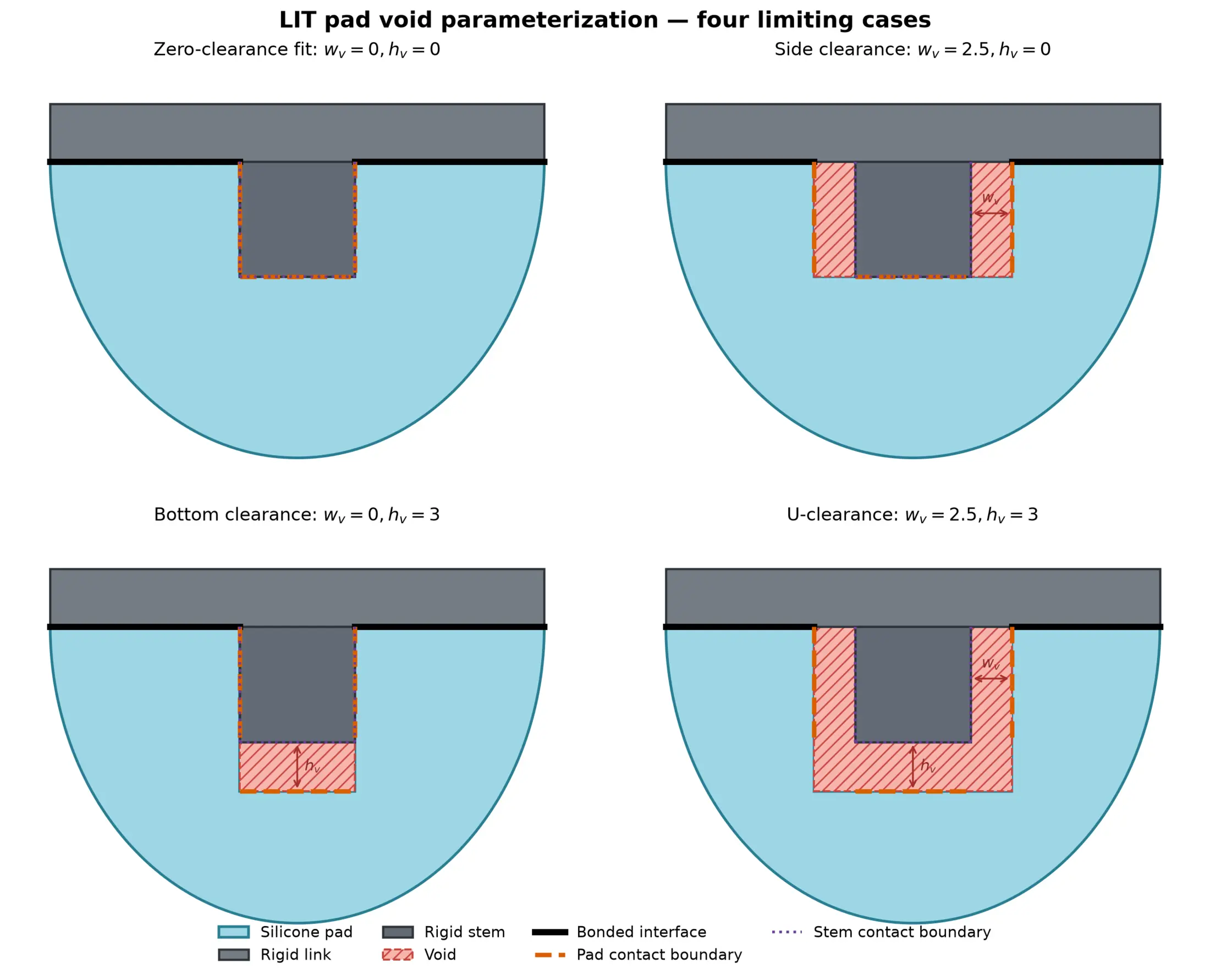
Two nonnegative clearance parameters generate four limiting topologies: zero-clearance fit, side clearance, bottom clearance, and U-clearance.
Two numbers change the topology
The rectangular cutout around the stem has
\[w_c = w_s + 2w_v, \qquad h_c = h_s + h_v.\]The rigid stem still occupies $w_s \times h_s$. The difference between the cutout and the stem becomes the void.
This produces four cases:
| $w_v$ | $h_v$ | Classification | Internal condition |
|---|---|---|---|
| 0 | 0 | zero-clearance fit | stem and pad boundaries begin coincident |
| $>0$ | 0 | side clearance | two side gaps, bottom remains coincident |
| 0 | $>0$ | bottom clearance | bottom gap, sides remain coincident |
| $>0$ | $>0$ | U-clearance | side and bottom gaps |
Geometrically, this is a small parameterization. Mechanically, it spans different problem classes.
With positive clearance, some internal boundaries begin separated and may contact only after deformation. With zero clearance, the surfaces begin coincident. The finite-element model must decide which body owns the contact multiplier, how the initial active set is constructed, and what happens at endpoints where a bonded boundary and a contact boundary meet.
The void is therefore not only “less material.” It changes the constraints.
Geometry must carry semantics
A common modeling mistake is to generate a polygon, mesh its outline, and infer boundary meaning later from node coordinates.
That approach becomes fragile as soon as the geometry changes. A line at $x=3.5$ might be the stem wall in one design, a pad cutout wall in another, and absent in a third. Floating-point tolerances and mesh refinement then decide which nodes receive a bond or contact condition.
The lit_ws model instead constructs named analytic boundaries:
PadBondLeftPadBondRightPadCutoutLeftPadCutoutRightPadCutoutBottomStemLeftStemRightStemBottomPadOuterArc
It also constructs three potential contact pairs—left, right, and bottom—with their initial normal gaps.
This separation lets geometry remain the single source of physical shape and boundary semantics. Meshing, Kratos setup, and plotting consume the same tags instead of rebuilding the meaning independently.
That architectural decision later made a subtle diagnosis possible: the left and right source geometry could be proven symmetric before the contact search generated an asymmetric candidate pair.
The admissible design space is not rectangular
It might appear that $w_v$ and $h_v$ can be swept independently over any nonnegative range. They cannot.
The lower corners of the cutout must remain inside the half-ellipse:
\[\left( \frac{w_s/2+w_v}{w_p/2} \right)^2 + \left( \frac{h_s+h_v}{h_p} \right)^2 \leq 1.\]The cutout must also leave positive bonded segments on both sides:
\[L_\text{bond,side} = \frac{w_p}{2} - \left(\frac{w_s}{2}+w_v\right) >0.\]These are not merely CAD validity checks. As the bonded length shrinks, the load path into the rigid plate changes. As the cutout approaches the outer arc, the remaining ligament becomes thin, bending-dominated, and increasingly sensitive to mesh resolution and manufacturing error.
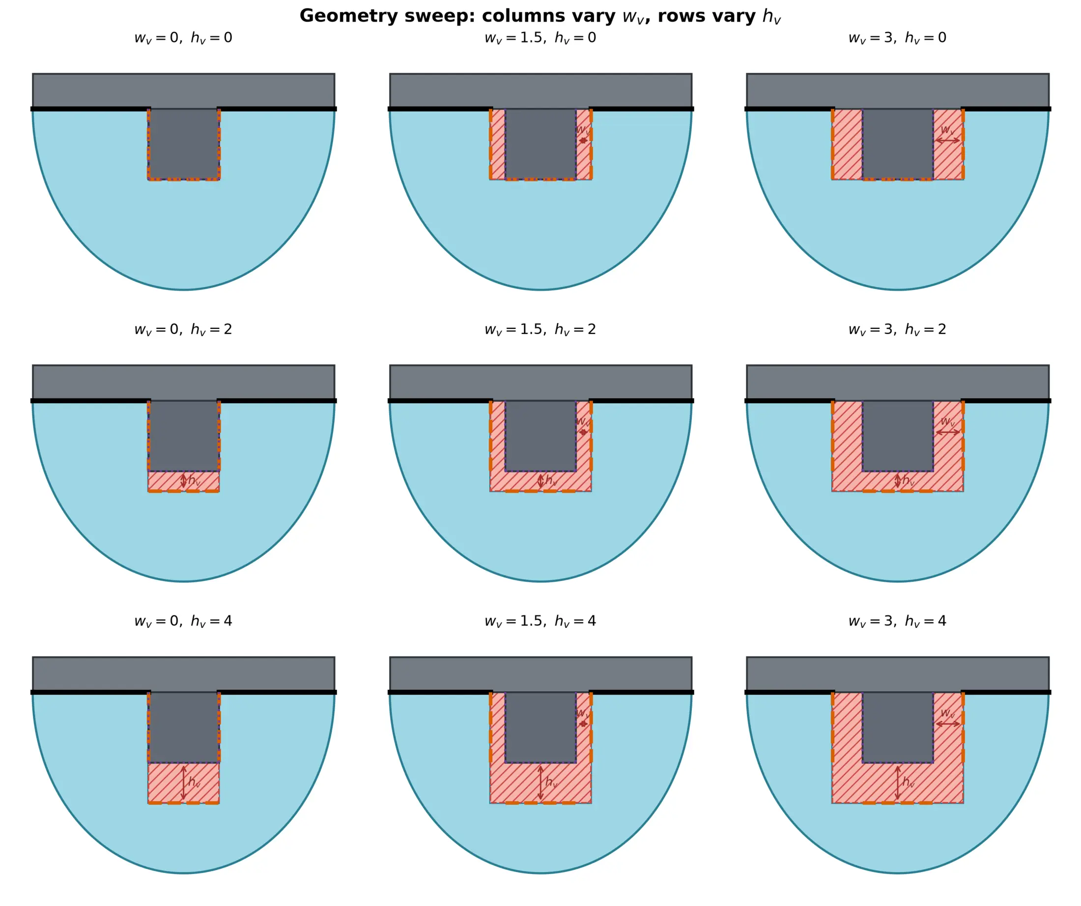
A parameter grid is useful only after invalid, disconnected, or nearly vanishing ligament geometries are rejected.
What this model can and cannot answer
The parameterization can answer geometry questions exactly:
- Is the material domain valid and connected?
- Which internal surfaces are coincident?
- How large is the void?
- How much bonded interface remains?
- Which boundaries must be tagged for external and internal contact?
It can also support controlled mechanical comparisons once a solver is attached.
It cannot, by itself, tell us that one design is a better sensor. A larger void may increase sidewall motion while also reducing load capacity, increasing strain concentration, introducing self-contact, or making the response highly nonlinear. A geometry explorer is not an optimizer.
The next step is to understand the load path. The rigid plate and stem do not only remove compliant material; they redirect deformation. That is where the difference between local indentation and global structural response begins.
Previous: A Robotic Fingertip Is Not a Rubber Cap · Series index · Next: Where Does the Internal Structure Send Deformation Energy?